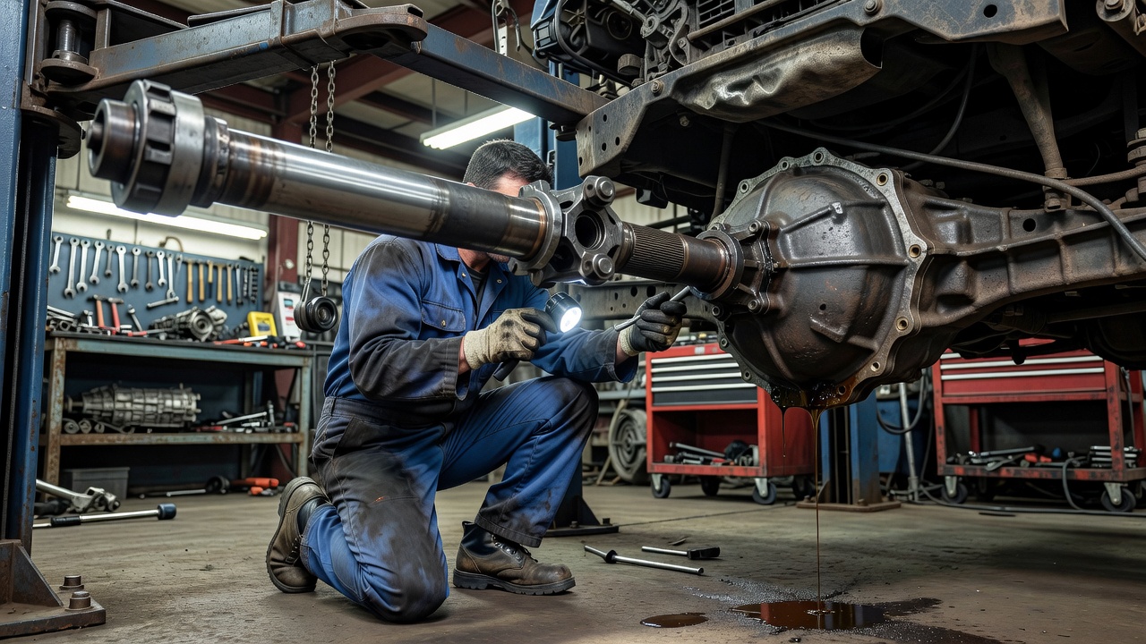
Draw the torque path first
Map the components between the engine and the contact patches: transmission, transfer case where fitted, propeller shafts, differentials, axle shafts or CV joints, hubs and wheels. Include control systems that alter torque delivery. This simple sketch helps identify which components see changed speed, torque or articulation after a modification.
A part-time four-wheel-drive system, a full-time system with a centre differential and an electronically controlled coupling do not behave identically. Read the vehicle handbook before deciding when to engage a mode. Using a locked connection between axles on an unsuitable high-grip surface can cause driveline wind-up where the system cannot accommodate the required speed difference.
Model names alone are not enough. Nissan Patrol, Suzuki Jimny, Ford Ranger, Mercedes-Benz G-Class and Mitsubishi Pajero ranges include different configurations across years and markets. Use the exact model, axle identification, transmission and transfer arrangement when seeking advice. A recommendation that worked for another vehicle may address a different architecture.
Understand what larger tyres change
For an unchanged mechanical gear ratio, increasing rolling diameter increases distance travelled per wheel revolution. At the same road speed, engine speed generally decreases in a fixed gear, but more torque at the wheel is required to generate the same tractive force. The transmission, clutch or torque converter may therefore work differently, especially on gradients or under load.
As a first approximation, preserving the original overall relationship requires a new axle ratio equal to the old ratio multiplied by new tyre diameter divided by old tyre diameter. This is a planning relationship, not a parts recommendation. Actual rolling circumference, available ratios, transmission behaviour and the vehicle’s intended work all matter.
Re-gearing is a specialist installation involving correct component matching, bearing setup and gear contact. Front and rear axle ratios in a conventional coupled four-wheel-drive arrangement must be appropriately matched. Tyre size and rolling-circumference differences also need to remain within the manufacturer’s requirements. Do not select parts using nominal tyre dimensions alone.
| Modification | Intended outcome | Linked concern |
|---|---|---|
| Larger rolling diameter | Selected clearance gains | Effective gearing, braking and joint loads |
| Differential lock | Traction when wheel loads differ | Steering behaviour and transferred torque |
| Suspension lift | Changed body or chassis clearance | Driveshaft angles and CV operating range |
Traction moves the limiting component
An open differential, a limited-slip unit and a selectable or automatic locker have different operating behaviours. A differential lock can help maintain drive when traction differs between wheels, but it can also change steering response and increase loads elsewhere. Engagement rules and speed restrictions are equipment-specific; follow the manufacturer rather than a generic trail habit.
Wheelspin followed by sudden grip can produce severe transient loads. A stronger shaft may move the failure into a joint, gearset or hub rather than eliminate it. Assess the whole assembly, including intended tyre size, vehicle mass, driving style and available traction. Controlled driving and suitable gearing can reduce demand more effectively than reinforcing one part in isolation.
Electronic traction control also belongs in the assessment. Some vehicles use brake intervention or integrated engine management, and aftermarket changes can affect those interactions. Do not assume that fitting a mechanical traction aid makes factory control logic irrelevant or that a warning light can safely be ignored.
Describe vibration before replacing parts
Record whether vibration tracks road speed, engine speed, acceleration, deceleration, steering angle or a particular gear. Note the surface and whether the vehicle is loaded. This evidence narrows the investigation without pretending to identify a fault remotely. Tyres, wheels, bearings, mounts and rotating shafts can produce overlapping symptoms.
After a lift, check driveline geometry against the exact shaft arrangement. Single-Cardan, double-Cardan and CV-based assemblies have different requirements. There is no universal pinion-angle correction. A qualified workshop should assess working angles, joint condition, balance and clearances with the relevant service information and safe inspection methods.
Do not run a supported vehicle in gear as an improvised diagnostic experiment. If there is looseness, severe vibration, new clunking or evidence of interference, stop and arrange inspection. Record recent work and share a clear fault report rather than buying a shaft, bearing or differential based on the sound alone.
Validate the whole build
After approved work, confirm lubricant specifications, breathers, seals and service intervals for the exact components. Extended breathers do not make a drivetrain waterproof, and a planned water crossing requires a separate assessment of depth, flow, environmental rules and vehicle limits. Check for contamination after exposure in accordance with the service guidance.
Keep a build record containing parts identification, alignment results, tyre dimensions and specialist setup documentation. When the next modification is proposed, revisit that record. A balanced drivetrain plan preserves predictable operation and a serviceable vehicle instead of repeatedly discovering the next weak link by breaking it.